


Xiuxin 2pcs 5V 8 Channel Relay Module Board for Arduino PIC AVR DSP ARM
Product ID: 62807245
Details
- BrandInfun
- Connector TypeThrough Hole
- Contact TypeNormally Open
- Current Rating10 Amps
- Mounting TypePCB Mount
⚡5V Power
🏠Smart Home Ready
🔌8 Channels
🔧 Control Your World with Precision!
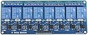
The Xiuxin 2pcs 5V 8 Channel Relay Module Board is designed for versatile applications, supporting various microcontrollers like Arduino, PIC, and ARM. With a working voltage of 5V, it can handle significant loads, making it perfect for both smart home automation and industrial control systems.
| ASIN | B07C8LSXKC |
| Brand | Infun |
| Coil Voltage | 5 Volts |
| Connector Type | Through Hole |
| Contact Current Rating | 10 Amps |
| Contact Type | Normally Open |
| Current Rating | 10 Amps |
| Date First Available | March 22, 2018 |
| Is Discontinued By Manufacturer | No |
| Item Weight | 7 ounces |
| Item model number | 8 channel |
| Manufacturer | Xiuxin |
| Maximum Switching Current | 10 Amps |
| Maximum Switching Voltage | 5 Volts |
| Mounting Type | PCB Mount |
| Operation Mode | Automatic |
| Product Dimensions | 5.28 x 2.09 x 0.67 inches |
| UPC | 666389676436 |
C**V
great for homeautomation
I used these to build a controller for my sprinkler system. The opto isolation allows the use of 3.3V microcontrollers to drive the relays provided you use a 5V supply to the relay coils. There is a jumper to select that option. Board quality is very good. I also use the 4 relay version of this board to control my HVAC system.
D**H
Good Value
Fast shipping. Easy to use. I control these using an ESP32-S3 board.
E**R
I wish NO or NC were marked
Overall these work fine. They are LOUD relays. I was frustrated that they don't have NO or NC marked. I mean, I can figure it out with a multimeter, but it would have been nice for them to be marked.
J**.
Worked great, as per specs
Used this with my Arduino/Elegoo set to control 110-volt circuits. Never had an issue with them.
M**D
A great quality relay board.
The two 8 relay parts arrived quickly. Build quality was top-notch with all channels working on both boards. I used these to switch 12V at 4A and so far so good. The circuit board around the relay's common output pin is milled to isolate this pin from the 5V coil pins. The NC and NO output side pins are way on the other side of the relay package. The optoisolators ground, however, is routed all around the optoisolator, from the opto part output side to the logic level input side. Logic drive is active low so the digital board driving this would need only to wire a +5V logic and the logic device pulls a control input low to activate a channel. Anyhow, it looks like a missed opportunity to isolate relay coil emf kickback or a failing relay structure. The optoisolator output side, in all cases, still needs a +5V power source. Even with this in mind, I gave 5 stars because driving a small relay coil using a non-optoisolated driver would be good enough.
D**T
Five Stars
These work wonderfully with my Raspberry Pi. Simple to use and very cost effective.
L**.
Nice modules
Arrived with no documentation. They're active low. An inline current measurement showed about 3mA (.003 A) of current draw.
T**E
No documents, highish power consumption
As usual, no instructions by manufacturer, have to rely on someone else's write-up. Power consumption of the relay coils on high side. Make sure you have a well regulated supply, or use a separate supply for the coils. There's a pin for it...
Trustpilot
3 weeks ago
2 weeks ago